 Why a membrane vessel is preferable to a diaphragm vessel
Varem has carried out a series of tests in its laboratories to test the operation of its vessels for pumping systems and compare them with other products on the market.
In particular, it carried out a series of parallel tests on vessels with balloon membrane and with diaphragm membrane, which offered proof of the significant superiority of the first solution, used by Varem, in given conditions and also drew attention to the limitations of the second solution.
|
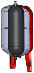
Membrane Vessel
|
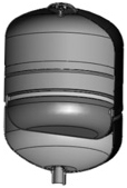
Diaphragm Vessel
|
 |
 |
The test carried out was the EN13831 cycle test indicated in the Directive PED 97/23/EC, which provides for correct operation of the product for 50,000 cycles at an average temperature of 30°C.
Naturally, one of the most important aspects for determining correct operation of an expansion vessel is the complete discharge of the water contained, for the whole duration of the test. Therefore, we carried out the tests also paying close attention to this aspect, monitoring the performances of the two products being compared in two situations: with pump shut down at 3 bar and at 5 bar.
Case 1: shut down pressure of 3 bar
 |
|
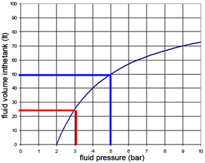
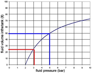
At a pump shut down pressure of 3 bar, the expansion vessel is filled with a usable volume of water equivalent to 25% of the nominal value. By way of example, a tank with a nominal value of 100 l contains 25 l of water.
In this configuration, comparison between the two types of tank showed that the test was passed without any problem.
|
Case 2: shut down pressure of 5 bar
 |
|
At a pump shut down pressure of 5 bar, the expansion vessel is filled with a usable volume of water equivalent to 50% of the nominal value. By way of example, a tank with a nominal value of 100 l contains 50 l of water.
In this configuration, comparison between the two types of tank showed a significant reduction in the discharge capacity of the diaphragm vessel, which starting from 4000 cycles was measured as 20%. In the case of the 100 l tank, the usable volume of water discharged decreased from the 50 l expected to 40 l.
|
Analysis of the tanks at the end of the 50,000 test cycles brought to light the reasons for this abnormal reaction of the diaphragm vessel.
The solution with shut down pressure of 5 bar caused yielding of the diaphragm membrane in the fastening area, as shown in the images below:
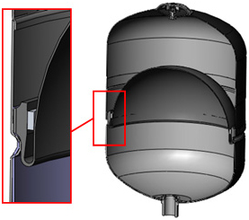
In fact, this area is subjected to increased stress as the pressure inside the vessel increases, contrary to membrane vessels in which the pressure is spread evenly over the whole of the surface of the membrane.
As a direct consequence of this, the diaphragm behaves abnormally, as indicated in the sequence of images below:

The rubber stretches until it blocks the water inlet/outlet before adhering fully to the inner walls of the vessel, retaining 20% of the usable volume of water inside the vessel.
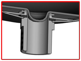
This situation creates two negative consequences for operation of the system:
- Increased electricity consumption
A reduction in the usable volume of water discharged causes a directly proportional increase in number of pump start-ups and consequently an increase in electricity consumption
- Decreased water quality
The presence of 20% of water retained inside the vessel, causing the problem of incorrect circulation of liquid with substantial stagnation, has the direct consequence of reducing the quality of water in systems used for sanitary water, as well as exposure to the risk of Legionella.
Therefore, we conclude that in systems with pressures in excess of 3 bar, the use of membrane vessels is highly recommended.
WATER LINE VERTICAL
- Vertical multifunction water tanks
- Replaceable membrane
- Available with galvanised or painted flange
- Red color
- Pre charge pressure 2 bar
LS-LSV
|
INTERVAREM LS CE
|
-10 + 99 °C
|
|
 |
|
Item
|
Std. Code.
|
Capacity
|
Max. pressure
|
Connection
|
Dimensions
|
Packaging
|
Qty/
pallet
|
| |
|
it
|
bar
|
inch
|
mm
|
m3
|
n.
|
|
LS 5
|
S2005361CS000000
|
5
|
8
|
1’
|
160x332
|
0.010
|
210
|
|
LS 8*
|
S2008361CS000000
|
8
|
8
|
1’
|
200x348
|
0.015
|
144
|
|
LS 12*
|
S2012361CS000000
|
12
|
8
|
1’
|
270x308
|
0.024
|
72
|
|
LS 19*
|
S2019361CS000000
|
19
|
8
|
1’
|
270x421
|
0.031
|
63
|
|
LS 20*
|
S2020361CS000000
|
20
|
10
|
1’
|
250x500
|
0.038
|
56
|
|
LS 24*
|
S2024361CS000000
|
24
|
8
|
1’
|
351x348
|
0.045
|
54
|
|
LS 25*
|
S2025361CS000000
|
25
|
8
|
1’
|
290x480
|
0.041
|
63
|
|
LS 40*
|
S2040361CS000000
|
40
|
10
|
1’
|
320x587
|
0.066
|
36
|
|
|
Available s/s flange and
blue ral 5051 upon request
* Available version in white color,
stainless steel flange and 3,5 bar
pre charge pressure
|
|
MAXIVAREM LS CE
|
-10 + 99 °C
|
|
 |
|
Item
|
Std.Code
|
Capacity
|
Max. pressure
|
Connection
|
Dimensions
|
Packaging
|
Qty/
pallet
|
| |
|
it
|
bar
|
inch
|
mm
|
m3
|
n.
|
|
LS V 50
|
US050361CS000000
|
50
|
10
|
1’
|
379x759
|
0.126
|
15
|
|
LS V 60
|
US060361CS000000
|
60
|
10
|
1’
|
379x815
|
0.131
|
15
|
|
LS V 80
|
US080361CS000000
|
80
|
10
|
1’
|
450x789
|
0.170
|
15
|
|
LS V 100
|
US100361CS000000
|
100
|
10
|
1’
|
450x910
|
0.200
|
15
|
|
LS V 150
|
US150461CS000000
|
150
|
10
|
1’1/2
|
554x1020
|
0.340
|
8
|
|
LS V 200
|
US200461CS000000
|
200
|
10
|
1’1/2
|
554x1213
|
0.407
|
8
|
|
LS V 300
|
US300461CS000000
|
300
|
10
|
1’1/2
|
624x1373
|
0.596
|
6
|
|
LS V 500
|
US500461CS000000
|
500
|
10
|
1’1/2
|
775x1460
|
1.300
|
1
|
|
LS V 750**
|
US750461CS000000
|
750
|
10
|
1’1/2
|
786x1925
|
2
|
1
|
|
LS V 1000**
|
USN10H61CS000000
|
1000
|
10
|
2’
|
933x1912
|
2.200
|
1
|
|
LS V 2000**
|
USN20H61CS000000
|
2000
|
10
|
2’
|
1280x2241
|
2.500
|
1
|
|
|
Available stailess steel flange and
blue ral 5051 upon request
** Available version not CE marked
also with capacity 1500 lt
|
LS H
|
Water Line
WATER LINE HORIZONTAL
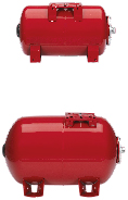
- Horizontal multifunction water tanks
- Replaceable membrane
- Available with galvanised or painted flange
- Red Color
- Pre charge pressure 2 bar
|
|
INTERVAREM - MAXIVAREM LS CE
|
-10 + 99 °C
|
|
 |
|
Item
|
Std. Code
|
Capacity
|
Max.
pressure
|
Connection
|
Dimensions
|
Packaging
|
Qty/
pallet
|
| |
|
it
|
bar
|
inch
|
mm
|
m3
|
n.
|
|
HORIZONTAL
|
|
LS H 19*
|
S2H19361CS0BP000
|
19
|
8
|
1’
|
270x421
|
0.031
|
63
|
|
LS H 20*
|
S2H20361CS0BP000
|
20
|
10
|
1’
|
250x500
|
0.038
|
56
|
|
LS H 40
|
US041361CS000000
|
40
|
10
|
1’
|
320x587
|
0.066
|
36
|
|
LS H 50
|
US051361CS000000
|
50
|
10
|
1’
|
379x759
|
0.126
|
15
|
|
LS H 60
|
US061361CS000000
|
60
|
10
|
1’
|
379x815
|
0.131
|
15
|
|
LS H 80
|
US081361CS000000
|
80
|
10
|
1’
|
450x789
|
0.170
|
15
|
|
LS H 100
|
US101361CS000000
|
100
|
10
|
1’
|
450x910
|
0.200
|
15
|
|
LS H 200
|
US201461CS000000
|
200
|
10
|
1’1/2
|
554x1213
|
0.407
|
8
|
|
LS H 300
|
US301461CS000000
|
300
|
10
|
1’1/2
|
624x1373
|
0.596
|
6
|
|
|
* Available version with s/s flange and
3,5 bar pre charge pressure
|
LSP – LS PV
|
Water Line
WATER LINE VERTICAL / HIGH PRESSURE
- Vertical multifunction water tanks
- Replaceable membrane
- Available with galvanised or painted flange
- Red color
- Pre charge pressure 2 bar
|
|
|
 |
|
Item
|
Std. Code
|
Capacity
|
Max.
pressure
|
Connection
|
Dimensions
|
Packaging
|
Qty/
pallet
|
| |
|
it
|
bar
|
inch
|
mm
|
m3
|
n.
|
|
HIGH PRESSURE
|
|
LS P 8
|
S5008361CS000000
|
8
|
16
|
1’
|
160x332
|
0.015
|
144
|
|
LS P 20
|
S5020361CS000000
|
20
|
16
|
1’
|
250x509
|
0.038
|
56
|
|
LS PV 50
|
S5050361CS000000
|
50
|
16
|
1’
|
379x759
|
0.128
|
15
|
|
LS PV 80
|
S5080361CS000000
|
80
|
16
|
1’
|
453x789
|
0.170
|
15
|
|
LS PV 100
|
S5100361CS000000
|
100
|
16
|
1’
|
453x915
|
0.200
|
15
|
|
LS PV 200
|
S5200461CS000000
|
200
|
16
|
1’1/2
|
556x1218
|
0.407
|
8
|
|
LS PV 300**
|
S5300461CS0CE000
|
300
|
14
|
1’1/2
|
626x1373
|
0.596
|
6
|
|
LS PV 500**
|
S5500461CS0CE000
|
500
|
12
|
1’1/2
|
777x1457
|
1.300
|
1
|
|
LS PV 750***
|
S5750461CS000000
|
750
|
16
|
1’1/2
|
786x1925
|
2
|
1
|
|
LS PV 1000***
|
S5N10H61CS000000
|
1000
|
16
|
2’
|
933x1912
|
2.200
|
1
|
|
|
Available version with s/s flange
22 bar upon request
** 16 bar available not marked ce
*** Not marked ce
|
최근 상담내역이 없습니다.


